This was discussed on muffwiggler with the idea of getting some clones made. I designed my own version of the circuit based on a description of the functions.
My version has 32 LEDs, gate/CV controlled up/down counting ability and will process audio or CV signals between +/-7V.
A friend dropped off his module for me to have a look at, I added the resistors to each of the 32 I/O connections and noted that Driscoll's logic was somewhat different to mine, although I am quite sure the result is the same.
This schematic is UNTESTED, when the PCBs are made and checked I will update this post.
update: a bit buggy this one. New better, faster, simpler version is HERE
nonlinearcircuits meets Serge & Driscoll
Monday, 3 February 2014
Monday, 15 July 2013
Wednesday, 10 July 2013
panel 1
Almost ready for final testing
A few broken wires and lifted pads on the 101 and 104 boards took some sorting.
Replaced most of the caps, new (and slightly overkill) power wires and a CGS power distro board.
Dog approves
A few broken wires and lifted pads on the 101 and 104 boards took some sorting.
Replaced most of the caps, new (and slightly overkill) power wires and a CGS power distro board.
Dog approves
Saturday, 29 June 2013
Additive Programmers 3
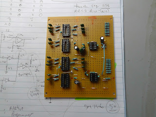
The DM7406 chips all tested fine, so decided to simply rebuild the boards. The vero-board has two additive programmers and a hi-gain pre-amp. Nearly finished wiring it up (only about 80 wires involved).
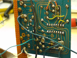
MC1494 Ring Modulator
This PCB pretty much follows the test circuit given in the datasheet, although I'd like to know where it came from. Please add a comment if you know - thanks.
It has not been tested yet. If the chip is okay, the components will get a makeover. If the chip is dead, the board will be replaced by an early Serge RM, as 1494s are a bit rare now.
see below for updates
Dave Jones of http://www.jonesvideo.com/ kindly gave me a bit of info on these - "The chips are dated late 1971 and early 1972.
Allowing for time in the supply chain the board is still probably from
the early 70s (1972/73).
The op amp might be an industrial part numbered UA741. (metal can pin numbers are the same as MC1456, but the marking contains 741 in it)
The board is virtually identical to the "typical" diagram from the data sheet. Right down to the trimpot I crossed out (board was laid out for it, but it was jumpered out).
The board has a spot for a pair of zeners that are independent of the rest of the circuit, except for one leg going to ground. But those parts aren't installed."
It has not been tested yet. If the chip is okay, the components will get a makeover. If the chip is dead, the board will be replaced by an early Serge RM, as 1494s are a bit rare now.
see below for updates
The op amp might be an industrial part numbered UA741. (metal can pin numbers are the same as MC1456, but the marking contains 741 in it)
The board is virtually identical to the "typical" diagram from the data sheet. Right down to the trimpot I crossed out (board was laid out for it, but it was jumpered out).
The board has a spot for a pair of zeners that are independent of the rest of the circuit, except for one leg going to ground. But those parts aren't installed."
Serge TKB
This took a bit of poking and prodding to get running again, the main problem turned out to be a semi-dead inverter chip.
Found some interesting mods on the PCB, not sure if this was due to an error with the PCB layout or the connector:
Found some interesting mods on the PCB, not sure if this was due to an error with the PCB layout or the connector:
Subscribe to:
Comments (Atom)


